2-Node vSAN deployments can be a great choice for remote office/branch office (ROBO) scenarios, as it can be managed by the same vCenter as your other infrastructure. Setting up the 2 nodes in a direct connect configuration can be beneficial if the remote site has a) limited switch port availability, or b) no 10GB switching available.
Note: Items in bold are of particular significance, as they were a sticking point for me during configuration. Paying attention to these items will save you a little trouble.
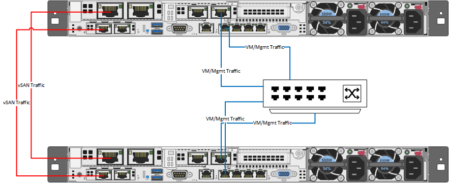
Each design will vary depending on network capabilities at the location, VM workload size, etc. In my case, we had limited network availability and a very light VM workload for our vSAN ROBO clusters. For our physical design, we directly connected two 10Gb ports for vSAN traffic, and two other ports for mgmt/VM/vMotion traffic. Our configuration incorporates NIC card/controller redundancy, as any configuration should. In a more demanding environment, I would recommend splitting the vMotion or VM traffic out onto its own vmk using separate ports. This image illustrates our logical wiring design (sans iLO).
For this setup, 6 IP addresses are needed:
- 1 routable management IP per host (ROBO site VLAN)
- 1 non-routable vSAN vmk IP per host (ROBO site non-routable VLAN)
- 1 routable management IP for witness appliance (Witness site VLAN)
- 1 routable witnessk vmk IP for witness appliance (alternate Witness site VLAN)
Once all the cabling and IP requirements have been satisfied, ESXi 6.7 can be installed following your normal procedures. Ensure that all disks that will be used by vSAN are configured in pass-through mode, and have caching disabled on their storage controller. Don’t forget to set the NTP server configuration on the hosts!
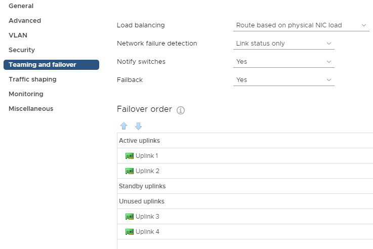
vSAN is completely dependent on proper network configuration and functionality, so it is important to take extra care during the setup of the DVS and port groups that the vSAN cluster will be using. In my case, these were the first vSphere deployments at their respective sites, so we created a new Distributed Virtual Switch (DVS) for each datacenter with 4 uplinks. Then, 2 port groups need to be created within those DVSs. The first port group is for host management, VM traffic, and vMotion and will be set to only use uplinks 1 and 2. Traffic on that port group will be load balanced based on physical NIC load.
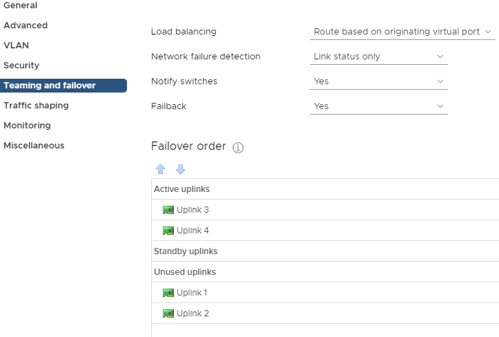
The second port group will be used for vSAN traffic only, and should be configured to only use uplinks 3 and 4.
At this point you’ll add your new hosts to the DVS. Assign the vmnic ports designated for management to the appropriate port group, and assign the vSAN vmnic ports to the newly created vSAN port group. Then, migrate the management vmk to the correct port group. The hosts should not be running anything through the standard vSwitch. This is a good opportunity to make sure you have vMotion enabled on the management vmk.
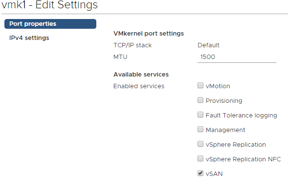
Add another VMkernel port and attach it to the vSAN port group, with vSAN being the only enabled service on the vmk. This will need to be done on each host.
Once you have the vSAN VMKs on each host, you can confirm the vSAN kernel ports can ping each other by running the below command from each host:
vmkping <IP of vsan VMK on target> -I vmk1
Update (3/19): as pointed out to me by Benjamin Colart, RDMA enabled network adapters require additional configuration, but you may choose to disable RDMA in the BIOS. Improper configuration of RDMA without disabling it may result in connectivity problems within your vSAN environment
vSAN 2-node deployments require a witness appliance to maintain quorum. The witness is simply another ESXi host running in an alternate site. VMware provides a virtual appliance available for download on their website that can be deployed within your environment. Deploy the OVF at your witness site, and be sure to split the witness and management networks onto different subnets. It will need to be configured similar to any other host in your environment. Upon completion, right click your witness site datacenter object in vCenter and add your witness host to it. Up until this point, the witness appliance was simply a VM running ESXi, but it needs to be added to vCenter as a host in order to function as a vSAN witness. Once added, navigate to the VMkernel configuration for the witness appliance and modify the witness vmk so it uses the static IP obtained earlier. Be sure to check the box to override the default gateway for the adapter, and enter the gateway for the subnet the vmk resides on.
Let’s stop for a moment and consider what’s configured:
- Two vSAN hosts are configured and reside within the ROBO site datacenter in vCenter.
- One witness appliance is configured and resides in the witness site datacenter in vCenter.
- A cluster has not yet been created, and vSAN is not enabled.
Before creating the vSAN cluster, patch the hosts and witness appliance to the latest version supported in your environment. It is recommended that the witness appliance runs at the same patch level as the nodes in the vSAN cluster.
In vCenter, create a new cluster within your ROBO site. Do not enable DRS or HA while creating the vSAN cluster object. Then, add the two vSAN hosts into the cluster. Within the cluster configuration, select vSAN -> Services and click Configure in the pane on the right. The vSAN configuration wizard will walk through the configuration of the core vSAN components:
- vSAN configuration type – Two host vSAN cluster
- Optional – enable deduplication and compression (for all flash storage hosts)
- Optional – enable encryption (with enterprise vSAN license)
- Claim disks for vSAN (see Associating NAA IDs with Physical Drive Bay Location on HPE Servers for help on HPE servers)
- Select the previously configured witness appliance host as the vSAN cluster witness
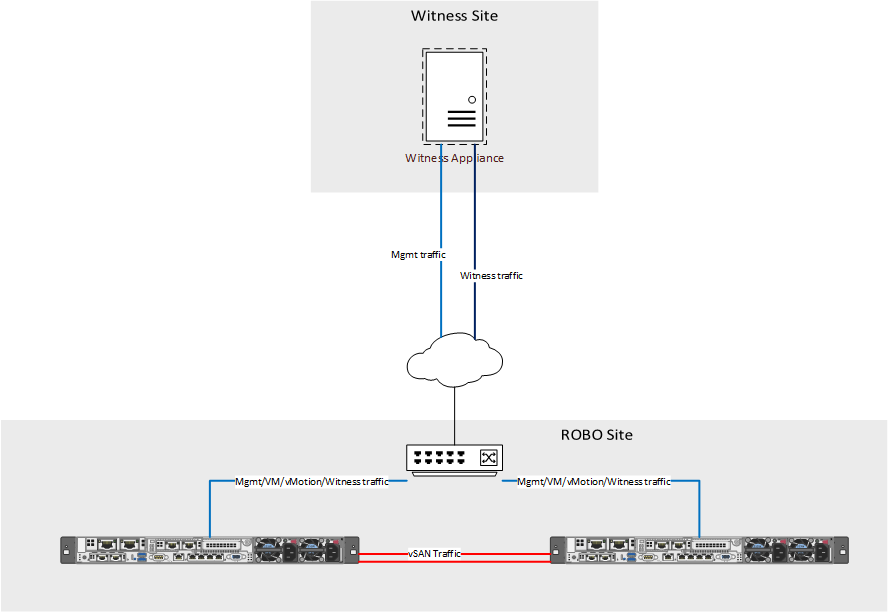
Typically, that is all that is required for enabling vSAN for two host deployments, however direct connect clusters require an additional step. By default, vSAN sends witness traffic over the vSAN network.
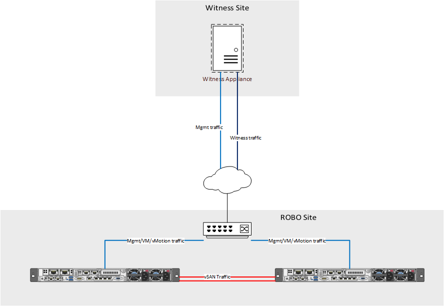
As can be seen in the image above, the vSAN network is directly connected to the other host, and is not routable for the witness. To fix the witness communication issue, a static route needs to be added to each of the vSAN hosts.
esxcli vsan network ip add -i vmk0 -T=witness
This command instructs the hosts to send any traffic destined for the witness to be sent out vmk0, which in this example is the management vmk. Once you have added the route to each host, run:
esxcli vsan network list
You should see vmk1 used for vSAN, and vmk0 used for witness traffic.
The only remaining tasks are to enable HA and DRS (license permitting) and to license the cluster. Within vCenter, navigate to your new vSAN cluster -> Monitor -> vSAN -> Health and run a retest of the vSAN health. Assuming everything else has been configured properly you should be welcomed by a screen of green check marks!
4 Comments
Nice document Wes!
Hello,
I’m trying to build the same config, but are you using straight cables or cross cables for direct connect of your ESXi 10GB?
Hi Benjamin,
I used normal (non-crossover) cat6a cables for my deployments, but crossover cables would have worked as well. In pretty much all modern hardware, the NICs will do the flip for you.
Hi,
nice blog post. But, are you sure, that can use two uplinks within the vsan port-group when you have a direct connection?
I had an issue after a planned maintenance. After reboot the two vsan nodes were not able to communicate anymore. I solved the issue by disabling one uplink of the port-group.
Have you ever had something similar.
Best regards,
Matthias