I ran into a situation lately where we had a disk throw a predictive failure alert on an HPE Proliant server at a remote site running VMware ESXi 6.7. Using the iLO is a great way to figure out which drive bay contains the failed drive, but it does not provide a mechanism to “blink” the UID so that the on-site technician can easily identify and replace the correct drive.
This particular server belonged to a vSAN cluster. vSAN disk management within vSphere provides the ability to be able to enable the LED on a drive, but that functionality did not work for us. In an earlier post, I found that I could use the Smart Storage Administrator CLI (SSACLI) utility that is included with the custom HPE ESXi iso in order to determine drive bay location, so I was wondering if we could use the same tool to enable the UID (blinking light) for a specific drive.
I found this guide on github which had a lot of great examples of the usage of the SSACLI utility, including the ability to enable the UID on a particular drive. First, I ran the blow command to list all of the disks in the server to confirm the bay location of the failed drive.
/opt/smartstorageadmin/ssacli/bin/ssaclictrl slot=0 pd all show detail
The output will look something like this, with an entry for each disk in the system:
physicaldrive 1I:1:4 Port: 1I Box: 1 Bay: 4 Status: OK Drive Type: Unassigned Drive Interface Type: Solid State SAS Size: 1.9 TB Drive exposed to OS: True Logical/Physical Block Size: 512/4096 Firmware Revision: HPD2 Serial Number: – WWID:58CE38EE2057D3C6 Model: HP MO001920JWFWU Current Temperature (C): 29 Maximum Temperature (C): 30 Usage remaining: 100.00% Power On Hours: 592 SSD Smart Trip Wearout: True
After identifying the failed drive, and its location of 1I:1:4, I can then tailor the command to enable the UID of that particular drive.
The above command will enable the UID for an hour, if you want to manually turn off the LED light before that, simply change the the parameter led=off.
Designing vSAN clusters with a failures to tolerate (FTT) value of 2 allows increased redundancy as well as reduced risk, especially during maintenance windows. However, that increase in redundancy comes at a storage cost. In all-flash solutions, that storage cost can be somewhat offset by leveraging vSAN RAID 6 (Erasure Coding) policies. When designing clusters with an FTT=2 using RAID 6 policies, there are several aspects to consider:
What is vSAN RAID 6 Erasure Coding?
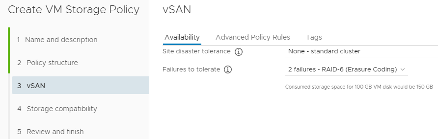
RAID 6 is a type of RAID that leverages 4 data bits with 2 parity bits. VMware vSAN uses erasure coding (a term that means to encode and partition data into fragments) to split data into the 4 data and 2 parity components. Those computations of erasure coding have a performance impact, and that is why VMware requires all flash storage in order to use RAID 6 erasure coding policies. The use of erasure coding affords a considerable capacity improvement. For example, when using RAID 1 for an FTT=2 policy, the storage multiplier is 3x – a 100GB VM will consume 300GB. With RAID 6, the storage multiplier is only 1.5x. That same 100GB VM will only consume 150GB. Check out the Virtual Block’s blog for some great info on the use of erasure coding in vSAN.
vSAN RAID 6 (Erasure Coding) Requirements
If you want to leverage RAID 6 erasure coding polices, the following requirements must be met:
vSAN Advanced license
The hosts in the cluster must use all-flash storage
The cluster must have at least 6 hosts
On-disk format version 3 or later for RAID 5/6 polices
Additional information on vSAN RAID 6 requirements can be found here.
Physical Host Layout
Before getting into vSAN configuration specifics, it is best practice to separate hosts physically. This is commonly accomplished by splitting hosts in a cluster among multiple racks. Those racks should be spread out as much as is possible. The only requirement is a sub-1ms RTT between hosts in the cluster. Given that using RAID 6 erasure coding policies have a minimum 6 host requirement, it would be ideal to split a cluster into 6 or more racks.
Use of Fault Domains
vSAN uses what is referred to as fault domains to represent the physical grouping of hosts. In many cases, one fault domain represents one rack of hosts. VMware’s documentation for managing fault domains on vSAN is very helpful, and I recommend giving it a read. However, that post indicates the formula for achieving FTT=2 with fault domains uses the formula 2*n+1 where n is the desired FTT value. Using that formula would indicate that 5 fault domains would be enough to satisfy the requirement. That formula does not hold true for RAID 6 policies. If you refer back to the the 6 components (4 data + 2 parity) used in RAID 6 policies, vSAN will distribute those components across the configured fault domains. In short, if you want to leverage fault domains with RAID 6 erasure coding policies, there must be at least 6 fault domains. If the cluster being designed has exactly 6 nodes, or an odd number of nodes, there is no drawbacks to putting only one host into a fault domain (even if other fault domains in the same cluster have more than one host). Although the use of fault domains is recommended, they are not required. RAID 6 policies will also work with no fault domains configured.
Configuring the RAID 6 Storage Policy
At this point, the only remaining piece of the “puzzle” is to set up the SPBM policy for RAID 6. Assuming everything is set up correctly, this will be the easiest part. Simply create a new Storage Policy and select “2 failures – RAID-6 (ErasureCoding)” for the failures to tolerate option under vSAN rules.
The next screen will show all of the vSAN datastores in your environment that are compatible with the RAID 6 policy. If you do not see the proper datastore in this list, change the drop down to show incompatible clusters, and hover over the incompatibility reason. If you see an error similar to “VASA provider is out of resources to satisfy this provisioning request”, or see symptoms outlined in VMware KB 2065479, verify that you have a proper fault domain count, and that they are configured properly.
With 2018 coming to a close, I thought I would share a pet project that I’ve thrown a little time into off and on for the past few months.
A good portion of my job in the first half of 2019 will be migrating hundreds of Microsoft Windows workloads from Hyper-V to vSphere. With any change in hypervisor, there are often steps that need to be completed on the VM to ensure proper functionality. My project has been to create a powershell module to facilitate those steps with Windows workloads.
With this 1.0.0 release, the module has three usable cmdlets:
Get-IPInfo – Harvests all network settings (any number of NICs, any number of IPs per NIC, and even supports WINS) from a server prior to migration into a CSV file.
Set-IPInfo – Injects the network settings collected by Get-IPInfo into the target workload post-migration. The injection leverages VMware Tools, and no network connectivity is required on the target VM! (Shoutout to Luc Dekens for his work on Invoke-VMScriptPlus v2)
Convert-SCSItoParavirtual – Converts the SCSI controller of the target VM to paravirtual. Most conversion tools leave the VMs running the LSI Logic SAS controller, but the paravirtual controller is recommended for high IO workloads. (Automates the steps for the Windows boot disk in the VMware KB: https://kb.vmware.com/s/article/1010398)
My hope is for the community to provide feedback on improvements to the existing cmdlets, and also offer up ideas on what other migration steps could be automated. If this project matures, I would like to get it added to the Powershell gallery and add support for other OS families.
Drop me a comment with an idea of how this module can be improved, and what you’d like to see added!
2-Node vSAN deployments can be a great choice for remote office/branch office (ROBO) scenarios, as it can be managed by the same vCenter as your other infrastructure. Setting up the 2 nodes in a direct connect configuration can be beneficial if the remote site has a) limited switch port availability, or b) no 10GB switching available.
Note: Items in bold are of particular significance, as they were a sticking point for me during configuration. Paying attention to these items will save you a little trouble.
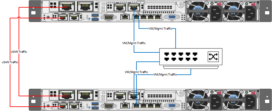
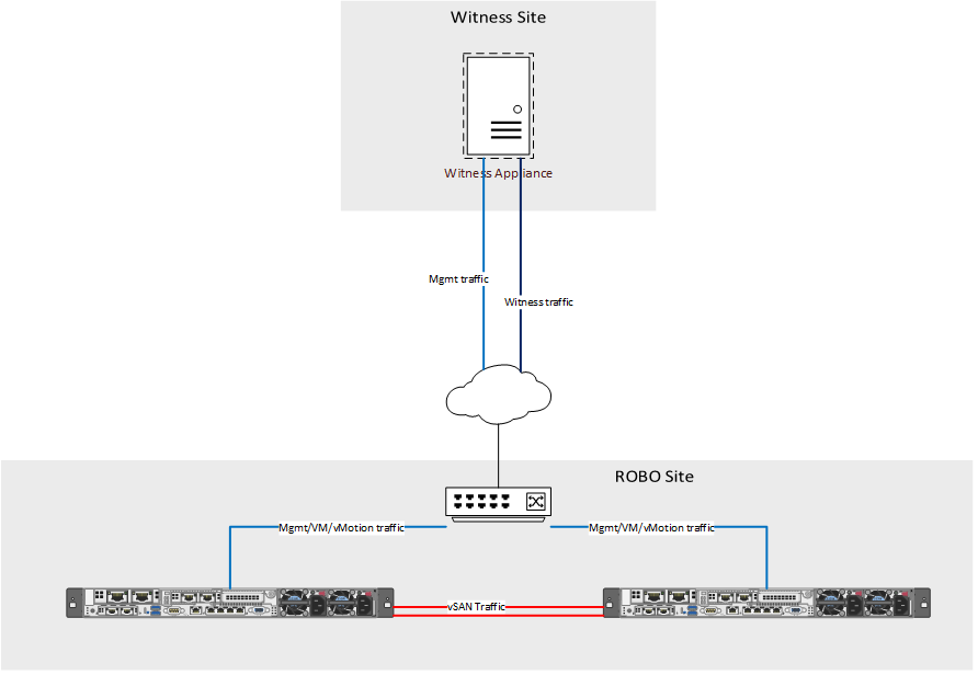
Each design will vary depending on network capabilities at the location, VM workload size, etc. In my case, we had limited network availability and a very light VM workload for our vSAN ROBO clusters. For our physical design, we directly connected two 10Gb ports for vSAN traffic, and two other ports for mgmt/VM/vMotion traffic. Our configuration incorporates NIC card/controller redundancy, as any configuration should. In a more demanding environment, I would recommend splitting the vMotion or VM traffic out onto its own vmk using separate ports. This image illustrates our logical wiring design (sans iLO).
For this setup, 6 IP addresses are needed:
1 routable management IP per host (ROBO site VLAN)
1 non-routable vSAN vmk IP per host (ROBO site non-routable VLAN)
1 routable management IP for witness appliance (Witness site VLAN)
1 routable witnessk vmk IP for witness appliance (alternate Witness site VLAN)
Once all the cabling and IP requirements have been satisfied, ESXi 6.7 can be installed following your normal procedures. Ensure that all disks that will be used by vSAN are configured in pass-through mode, and have caching disabled on their storage controller. Don’t forget to set the NTP server configuration on the hosts!
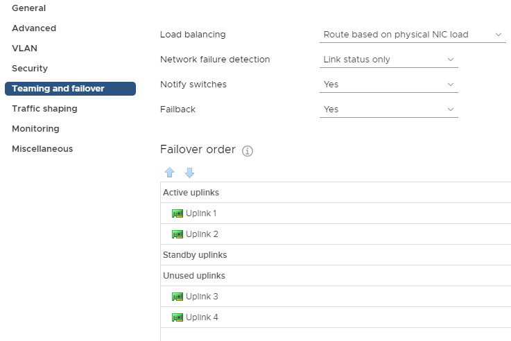
vSAN is completely dependent on proper network configuration and functionality, so it is important to take extra care during the setup of the DVS and port groups that the vSAN cluster will be using. In my case, these were the first vSphere deployments at their respective sites, so we created a new Distributed Virtual Switch (DVS) for each datacenter with 4 uplinks. Then, 2 port groups need to be created within those DVSs. The first port group is for host management, VM traffic, and vMotion and will be set to only use uplinks 1 and 2. Traffic on that port group will be load balanced based on physical NIC load.
Management, VM, and vMotion traffic port group configuration
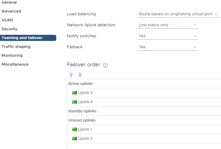
The second port group will be used for vSAN traffic only, and should be configured to only use uplinks 3 and 4.
vSAN port group configuration
At this point you’ll add your new hosts to the DVS. Assign the vmnic ports designated for management to the appropriate port group, and assign the vSAN vmnic ports to the newly created vSAN port group. Then, migrate the management vmk to the correct port group. The hosts should not be running anything through the standard vSwitch. This is a good opportunity to make sure you have vMotion enabled on the management vmk.
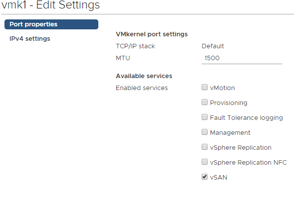
Add another VMkernel port and attach it to the vSAN port group, with vSAN being the only enabled service on the vmk. This will need to be done on each host.
Once you have the vSAN VMKs on each host, you can confirm the vSAN kernel ports can ping each other by running the below command from each host:
vmkping <IP of vsan VMK on target> -I vmk1
Update (3/19): as pointed out to me by Benjamin Colart, RDMA enabled network adapters require additional configuration, but you may choose to disable RDMA in the BIOS. Improper configuration of RDMA without disabling it may result in connectivity problems within your vSAN environment
vSAN 2-node deployments require a witness appliance to maintain quorum. The witness is simply another ESXi host running in an alternate site. VMware provides a virtual appliance available for download on their website that can be deployed within your environment. Deploy the OVF at your witness site, and be sure to split the witness and management networks onto different subnets. It will need to be configured similar to any other host in your environment. Upon completion, right click your witness site datacenter object in vCenter and add your witness host to it. Up until this point, the witness appliance was simply a VM running ESXi, but it needs to be added to vCenter as a host in order to function as a vSAN witness. Once added, navigate to the VMkernel configuration for the witness appliance and modify the witness vmk so it uses the static IP obtained earlier. Be sure to check the box to override the default gateway for the adapter, and enter the gateway for the subnet the vmk resides on.
Let’s stop for a moment and consider what’s configured:
Two vSAN hosts are configured and reside within the ROBO site datacenter in vCenter.
One witness appliance is configured and resides in the witness site datacenter in vCenter.
A cluster has not yet been created, and vSAN is not enabled.
Before creating the vSAN cluster, patch the hosts and witness appliance to the latest version supported in your environment. It is recommended that the witness appliance runs at the same patch level as the nodes in the vSAN cluster.
In vCenter, create a new cluster within your ROBO site. Do not enable DRS or HA while creating the vSAN cluster object. Then, add the two vSAN hosts into the cluster. Within the cluster configuration, select vSAN -> Services and click Configure in the pane on the right. The vSAN configuration wizard will walk through the configuration of the core vSAN components:
vSAN configuration type – Two host vSAN cluster
Optional – enable deduplication and compression (for all flash storage hosts)
Select the previously configured witness appliance host as the vSAN cluster witness
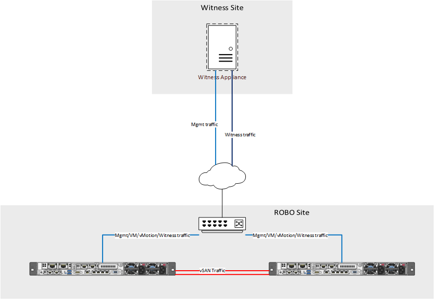
Typically, that is all that is required for enabling vSAN for two host deployments, however direct connect clusters require an additional step. By default, vSAN sends witness traffic over the vSAN network.
As can be seen in the image above, the vSAN network is directly connected to the other host, and is not routable for the witness. To fix the witness communication issue, a static route needs to be added to each of the vSAN hosts.
esxcli vsan network ip add -i vmk0 -T=witness
This command instructs the hosts to send any traffic destined for the witness to be sent out vmk0, which in this example is the management vmk. Once you have added the route to each host, run:
esxcli vsan network list
You should see vmk1 used for vSAN, and vmk0 used for witness traffic.
Witness traffic is now running through the management vmk
The only remaining tasks are to enable HA and DRS (license permitting) and to license the cluster. Within vCenter, navigate to your new vSAN cluster -> Monitor -> vSAN -> Health and run a retest of the vSAN health. Assuming everything else has been configured properly you should be welcomed by a screen of green check marks!