My Take: Ixia’s Visibility Portfolio – As Seen at Tech Field Day 19

Disclaimer: As an attendee of Tech Field Day 19, my flights, accommodations, and other expenses were paid for by Tech Field Day. I was not required to write about any of the content presented, and I have not been compensated in any way for this post. Some presenting companies chose to provide gifts to attendees; any such gifts do not impact my reviews or opinions as expressed on this site. All opinions in this post are my own, and do not necessarily represent that of my employer or Gestalt IT.

The first presenting company of Tech Field Day 19 (TFD19) was Ixia. The focus of their presentation surrounded their network visibility offerings. I’m not going to elaborate on all of the details of their presentations. I would instead encourage you to check them out:

My Thoughts

Although I have a pretty solid understanding of networking principles and regularly spend time troubleshooting problems around the network stack, the products in Ixia’s visibility platform are beyond the scope of what I do daily. Despite that, it’s easy to see where their product line would fit into an enterprise company. They strive to offer increased visibility into network traffic from the datacenter, to the edge, and all the way to the cloud. Companies need to increase security within their networks, but they can’t do that without knowing what is happening within them.

“The number one driver for visibility is security.”

Recep Ozdag – VP and GM of Network Visibility, Ixia

They leverage network taps to pass traffic, packet brokers to organize, aggregate and filter traffic, and also offer options to do the same in the cloud. You are then able to wrap rules and policies around the packet brokers to dictate what traffic is directed to your existing network security tool set, and how much of it. If that seems a little confusing, this diagram of theirs may help.

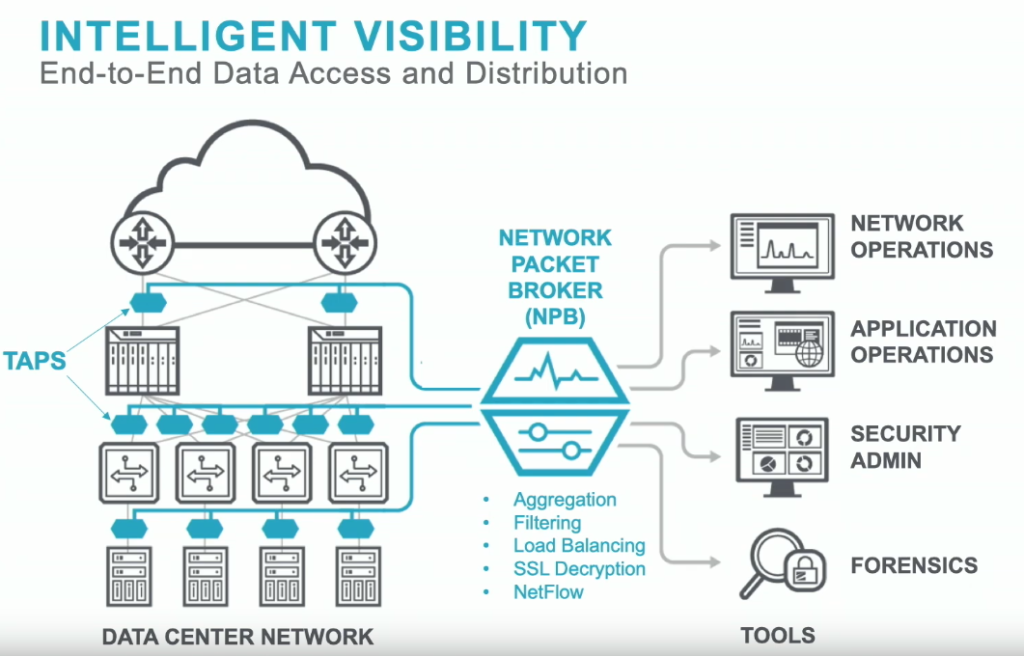
You may be asking yourself, “Why would I want this?” Perimeter security is great, but it is only a small part of the picture when it comes to securing a network. Enterprise networks create an immense amount of traffic, a large portion of which never touches the perimeter. Trying to funnel all of that traffic through a traditional set of security tools will likely overrun what the tools are capable of processing, or will land you a crazy-high licensing bill for those tools whose pricing are based on ingestion rates. That’s where the beauty of the traffic broker comes in. It allows you to wrap policies around traffic flow to intelligently trim and route packets to your existing security tools in order to maximize their utility.

I’m not going to get any further into the weeds on how it all works (that’s what the presentations are for). If you’re wondering if this type of product is right for you, let’s take a look at this customer statistic they displayed:

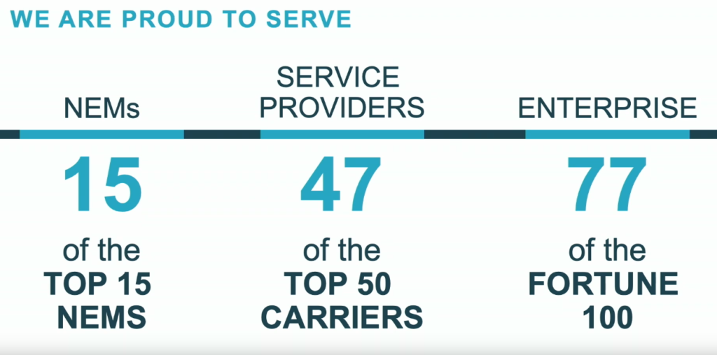
Those are some impressive numbers on large companies! However, my guess is that’s because their product is geared towards those large companies. I would be interested to see their customer numbers in the small/medium sized business areas.

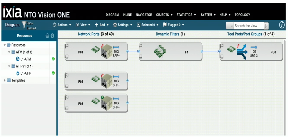
Unfortunately, Ixia only had an hour to present at TFD19 and likely didn’t have time to do a demonstration of the platform. They did show us a few screenshots of the UI, and honestly it felt a little dated. I can’t speak to the usability of the interface as I didn’t see it in action, but it does remind me of the iLO2 interfaces from the HPE days of old. Given their customer base, I would assume that the interface functions as expected. I was just hoping for something a little more modern.

TL;DR

Even though the UI leaves a little to be desired, Ixia offers a comprehensive portfolio of products that will help collect, aggregate, and filter network packets in order to maximize the effectiveness of a customer’s existing security tools. I would love to see how Ixia can tailor a solution to help the small businesses of the world achieve similar visibility.

Continue Reading

Presentation of “vSAN 2-Node Clusters: From Planning to Production”

Recently I had the opportunity to present on my journey deploying vSAN 2-node clusters at the Central Ohio VMUG UserCon, as well as a local Pittsburgh VMUG event. Overall, it was a great experience and I’m thankful to have had the opportunity! Check out the recording of the session below, and don’t forget to check out my post on Building a 2-node Direct Connect vSAN cluster.

Feel free to download the slide deck for this presentation.

Thanks to Ariel Sanchez for not only recording the session and uploading to the vBrownBag channel, but for pushing me to give this presentation in the first place!

Continue Reading

Designing vSAN Clusters for RAID 6

Designing vSAN clusters with a failures to tolerate (FTT) value of 2 allows increased redundancy as well as reduced risk, especially during maintenance windows. However, that increase in redundancy comes at a storage cost. In all-flash solutions, that storage cost can be somewhat offset by leveraging vSAN RAID 6 (Erasure Coding) policies. When designing clusters with an FTT=2 using RAID 6 policies, there are several aspects to consider:

What is vSAN RAID 6 Erasure Coding?

RAID 6 is a type of RAID that leverages 4 data bits with 2 parity bits. VMware vSAN uses erasure coding (a term that means to encode and partition data into fragments) to split data into the 4 data and 2 parity components. Those computations of erasure coding have a performance impact, and that is why VMware requires all flash storage in order to use RAID 6 erasure coding policies. The use of erasure coding affords a considerable capacity improvement. For example, when using RAID 1 for an FTT=2 policy, the storage multiplier is 3x – a 100GB VM will consume 300GB. With RAID 6, the storage multiplier is only 1.5x. That same 100GB VM will only consume 150GB. Check out the Virtual Block’s blog for some great info on the use of erasure coding in vSAN.

vSAN RAID 6 (Erasure Coding) Requirements

If you want to leverage RAID 6 erasure coding polices, the following requirements must be met:

  • vSAN Advanced license
  • The hosts in the cluster must use all-flash storage
  • The cluster must have at least 6 hosts
  • On-disk format version 3 or later for RAID 5/6 polices

Additional information on vSAN RAID 6 requirements can be found here.

Physical Host Layout

Before getting into vSAN configuration specifics, it is best practice to separate hosts physically. This is commonly accomplished by splitting hosts in a cluster among multiple racks. Those racks should be spread out as much as is possible. The only requirement is a sub-1ms RTT between hosts in the cluster. Given that using RAID 6 erasure coding policies have a minimum 6 host requirement, it would be ideal to split a cluster into 6 or more racks.

Use of Fault Domains

vSAN uses what is referred to as fault domains to represent the physical grouping of hosts. In many cases, one fault domain represents one rack of hosts. VMware’s documentation for managing fault domains on vSAN is very helpful, and I recommend giving it a read. However, that post indicates the formula for achieving FTT=2 with fault domains uses the formula 2*n+1 where n is the desired FTT value. Using that formula would indicate that 5 fault domains would be enough to satisfy the requirement. That formula does not hold true for RAID 6 policies. If you refer back to the the 6 components (4 data + 2 parity) used in RAID 6 policies, vSAN will distribute those components across the configured fault domains. In short, if you want to leverage fault domains with RAID 6 erasure coding policies, there must be at least 6 fault domains. If the cluster being designed has exactly 6 nodes, or an odd number of nodes, there is no drawbacks to putting only one host into a fault domain (even if other fault domains in the same cluster have more than one host). Although the use of fault domains is recommended, they are not required. RAID 6 policies will also work with no fault domains configured.

Configuring the RAID 6 Storage Policy

At this point, the only remaining piece of the “puzzle” is to set up the SPBM policy for RAID 6. Assuming everything is set up correctly, this will be the easiest part. Simply create a new Storage Policy and select “2 failures – RAID-6 (ErasureCoding)” for the failures to tolerate option under vSAN rules.

The next screen will show all of the vSAN datastores in your environment that are compatible with the RAID 6 policy. If you do not see the proper datastore in this list, change the drop down to show incompatible clusters, and hover over the incompatibility reason. If you see an error similar to “VASA provider is out of resources to satisfy this provisioning request”, or see symptoms outlined in VMware KB 2065479, verify that you have a proper fault domain count, and that they are configured properly.

Continue Reading

Introducing the vSphere Migration Toolkit

With 2018 coming to a close, I thought I would share a pet project that I’ve thrown a little time into off and on for the past few months.

A good portion of my job in the first half of 2019 will be migrating hundreds of Microsoft Windows workloads from Hyper-V to vSphere. With any change in hypervisor, there are often steps that need to be completed on the VM to ensure proper functionality. My project has been to create a powershell module to facilitate those steps with Windows workloads.

With this 1.0.0 release, the module has three usable cmdlets:

  • Get-IPInfo – Harvests all network settings (any number of NICs, any number of IPs per NIC, and even supports WINS) from a server prior to migration into a CSV file.
  • Set-IPInfo – Injects the network settings collected by Get-IPInfo into the target workload post-migration. The injection leverages VMware Tools, and no network connectivity is required on the target VM! (Shoutout to Luc Dekens for his work on Invoke-VMScriptPlus v2)
  • Convert-SCSItoParavirtual – Converts the SCSI controller of the target VM to paravirtual. Most conversion tools leave the VMs running the LSI Logic SAS controller, but the paravirtual controller is recommended for high IO workloads. (Automates the steps for the Windows boot disk in the VMware KB: https://kb.vmware.com/s/article/1010398)

The module can be reviewed and downloaded from my Github repo: https://github.com/wmilliron/vSphere-MTK

My hope is for the community to provide feedback on improvements to the existing cmdlets, and also offer up ideas on what other migration steps could be automated. If this project matures, I would like to get it added to the Powershell gallery and add support for other OS families.

Drop me a comment with an idea of how this module can be improved, and what you’d like to see added!

Continue Reading

Building a 2-Node Direct Connect vSAN 6.7 Cluster for ROBO

2-Node vSAN deployments can be a great choice for remote office/branch office (ROBO) scenarios, as it can be managed by the same vCenter as your other infrastructure. Setting up the 2 nodes in a direct connect configuration can be beneficial if the remote site has a) limited switch port availability, or b) no 10GB switching available.

Note: Items in bold are of particular significance, as they were a sticking point for me during configuration. Paying attention to these items will save you a little trouble.

Each design will vary depending on network capabilities at the location, VM workload size, etc. In my case, we had limited network availability and a very light VM workload for our vSAN ROBO clusters. For our physical design, we directly connected two 10Gb ports for vSAN traffic, and two other ports for mgmt/VM/vMotion traffic. Our configuration incorporates NIC card/controller redundancy, as any configuration should. In a more demanding environment, I would recommend splitting the vMotion or VM traffic out onto its own vmk using separate ports. This image illustrates our logical wiring design (sans iLO).

For this setup, 6 IP addresses are needed:

  • 1 routable management IP per host (ROBO site VLAN)
  • 1 non-routable vSAN vmk IP per host (ROBO site non-routable VLAN)
  • 1 routable management IP for witness appliance (Witness site VLAN)
  • 1 routable witnessk vmk IP for witness appliance (alternate Witness site VLAN)

Once all the cabling and IP requirements have been satisfied, ESXi 6.7 can be installed following your normal procedures. Ensure that all disks that will be used by vSAN are configured in pass-through mode, and have caching disabled on their storage controller. Don’t forget to set the NTP server configuration on the hosts!

vSAN is completely dependent on proper network configuration and functionality, so it is important to take extra care during the setup of the DVS and port groups that the vSAN cluster will be using. In my case, these were the first vSphere deployments at their respective sites, so we created a new Distributed Virtual Switch (DVS) for each datacenter with 4 uplinks. Then, 2 port groups need to be created within those DVSs. The first port group is for host management, VM traffic, and vMotion and will be set to only use uplinks 1 and 2. Traffic on that port group will be load balanced based on physical NIC load. 

Management, VM, and vMotion traffic port group configuration

The second port group will be used for vSAN traffic only, and should be configured to only use uplinks 3 and 4.

vSAN port group configuration

At this point you’ll add your new hosts to the DVS. Assign the vmnic ports designated for management to the appropriate port group, and assign the vSAN vmnic ports to the newly created vSAN port group. Then, migrate the management vmk to the correct port group. The hosts should not be running anything through the standard vSwitch. This is a good opportunity to make sure you have vMotion enabled on the management vmk.

Add another VMkernel port and attach it to the vSAN port group, with vSAN being the only enabled service on the vmk. This will need to be done on each host.

vSAN vmk configuration

Once you have the vSAN VMKs on each host, you can confirm the vSAN kernel ports can ping each other by running the below command from each host:

vmkping <IP of vsan VMK on target> -I vmk1

Update (3/19): as pointed out to me by Benjamin Colart, RDMA enabled network adapters require additional configuration, but you may choose to disable RDMA in the BIOS. Improper configuration of RDMA without disabling it may result in connectivity problems within your vSAN environment

vSAN 2-node deployments require a witness appliance to maintain quorum. The witness is simply another ESXi host running in an alternate site. VMware provides a virtual appliance available for download on their website that can be deployed within your environment. Deploy the OVF at your witness site, and be sure to split the witness and management networks onto different subnets. It will need to be configured similar to any other host in your environment. Upon completion, right click your witness site datacenter object in vCenter and add your witness host to it. Up until this point, the witness appliance was simply a VM running ESXi, but it needs to be added to vCenter as a host in order to function as a vSAN witness. Once added, navigate to the VMkernel configuration for the witness appliance and modify the witness vmk so it uses the static IP obtained earlier. Be sure to check the box to override the default gateway for the adapter, and enter the gateway for the subnet the vmk resides on.

Let’s stop for a moment and consider what’s configured:

  • Two vSAN hosts are configured and reside within the ROBO site datacenter in vCenter.
  • One witness appliance is configured and resides in the witness site datacenter in vCenter.
  • A cluster has not yet been created, and vSAN is not enabled.

Before creating the vSAN cluster, patch the hosts and witness appliance to the latest version supported in your environment. It is recommended that the witness appliance runs at the same patch level as the nodes in the vSAN cluster.

In vCenter, create a new cluster within your ROBO site. Do not enable DRS or HA while creating the vSAN cluster object. Then, add the two vSAN hosts into the cluster. Within the cluster configuration, select vSAN -> Services and click Configure in the pane on the right. The vSAN configuration wizard will walk through the configuration of the core vSAN components: 

  • vSAN configuration type – Two host vSAN cluster
  • Optional –  enable deduplication and compression (for all flash storage hosts)
  • Optional – enable encryption (with enterprise vSAN license)
  • Claim disks for vSAN (see Associating NAA IDs with Physical Drive Bay Location on HPE Servers for help on HPE servers)
  • Select the previously configured witness appliance host as the vSAN cluster witness

Typically, that is all that is required for enabling vSAN for two host deployments, however direct connect clusters require an additional step. By default, vSAN sends witness traffic over the vSAN network. 

As can be seen in the image above, the vSAN network is directly connected to the other host, and is not routable for the witness. To fix the witness communication issue, a static route needs to be added to each of the vSAN hosts.

esxcli vsan network ip add -i vmk0 -T=witness

This command instructs the hosts to send any traffic destined for the witness to be sent out vmk0, which in this example is the management vmk. Once you have added the route to each host, run:

esxcli vsan network list

You should see vmk1 used for vSAN, and vmk0 used for witness traffic.

Witness traffic is now running through the management vmk

The only remaining tasks are to enable HA and DRS (license permitting) and to license the cluster. Within vCenter, navigate to your new vSAN cluster -> Monitor -> vSAN -> Health and run a  retest of the vSAN health. Assuming everything else has been configured properly you should be welcomed by a screen of green check marks!

Continue Reading